 | Support Menu |  |
|
|
 |
 | Pinouts |  |
 |  |
|
SENSOR CABLE PIN OUTS
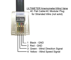
Please click the following links for diagrams showing sensor cable pinouts:
SERIAL PORT PIN OUTS & SERIAL CABLE WIRING
CAUTION: Regulated voltage is brought to the serial output receptacle on the older-model ULTIMETER 2000 and 500 (1998 and earlier). The regulator is likely to be damaged if you accidentally reverse the sequence of serial cable wires. On newer models, no damage will occur, but the weather station will not function. If you plan to make a serial interface cable, we urge you to take the following steps to avoid malfunction and possible damage when wiring a modular/DB-9 or modular/DB-25 adapter:
- Examine the standard modular phone cord you intend to use, to determine on which end the color sequence of wires matches the color sequence of wires on the adapter.
- Plug the matching end of the cord into the adapter.
- Wire color will now be continuous from the modular plug at one end, to the adapter insert pins at the other end, so you can use wire color as a guide determining which two or three pins to insert in the required numbered holes of the adapter.
- Connect only the required wires and individually insulate all unused wires.
|
MODEL 2100, 800 PIN # AND FUNCTION |
MODEL 100 PIN # AND FUNCTION |
MODEL II PIN # AND FUNCTION |
DB-9 to COMPUTER |
DB-25 to COMPUTER |
DB-9 to TNC |
DB-25 to TNC |
|
1 |
SPECIAL |
1 |
SPECIAL |
- |
- |
- |
- |
- |
- |
|
2 |
+5 VOLTS |
2 |
+5 VOLTS |
1 |
N/C |
- |
- |
- |
- |
|
3 |
OUTPUT |
3 |
OUTPUT |
2 |
OUTPUT |
PIN 2 |
PIN 3 |
PIN 3 |
PIN 2 |
|
4 |
HUMIDITY |
4 |
N/C |
3 |
N/C |
- |
- |
- |
- |
|
5 |
GROUND |
5 |
GROUND |
4 |
GROUND |
PIN 5 |
PIN 7 |
PIN 5 |
PIN 7 |
|
6 |
INPUT |
6 |
INPUT |
- |
- |
PIN 3 |
PIN 2 |
PIN 2 |
PIN 3 |
| MODULAR PHONE RECEPTACLE PINS ARE LABELED FROM LEFT TO RIGHT, LOOKING INTO THE FEMALE RECEPTACLE WITH THE RELEASE CLIP ON THE TOP. |
"Keep a weather eye on Peet Bros." |
|
|
|
 |
|